|
I work on a variety of multi-family housing projects, including residential apartment buildings and senior living facilities, where each dwelling unit has its own washer and dryer. In the past, I have always seen the dryer exhaust duct routed through a wall and then into the cavity of a floor-ceiling assembly, but on a recent project, the local AHJ questioned the validity of this approach. Code Requirements for Dryer Vent InstallationThis post is a summary of the code requirements and my suggestions for the most straight-forward way to handle the situation. All code references are the 2021 ICC Codes. Challenge 1: No Dampers PermittedThe first challenge when approaching dryer exhaust ducts is that the International Mechanical Code (IMC) Section 504.2 specifically prohibits the installation of fire dampers or combination fire/smoke dampers. If your dryer exhaust duct does not penetrate a rated wall or floor assembly, then you likely have no issue. However, since no one wants to look at a dryer exhaust duct running through their apartment, most designers choose to route the duct into the ceiling and then out of the building. This leads us to challenge 2. Challenge 2: Dampers Required at Floor/Ceiling Penetrations A duct that penetrates the ceiling of a floor/ceiling assembly and then runs horizontally through the floor cavity and out of the building would be considered a membrane penetration. IMC Section 607.6.2 requires that duct membrane penetrations of a rated floor/ceiling or roof/ceiling assembly be protected with either a listed ceiling radiation damper or a shaft enclosure (there is a similar requirement in IBC Section 717.6.2). We already know from our first challenge that a damper is not permitted, so that seemingly leaves a shaft enclosure as the only option. Again, it’s undesirable to building residents or designers to have a shaft enclosure simply to protect a dryer exhaust duct. Solution: Dryer Vent InstallationFortunately, a straight-forward solution is found in IBC 717.6.2.2, Exception 2. The exception here allows for the omission of a damper at the ceiling membrane penetration when the duct is protected in accordance with IBC Section 714.5.2, is located within the cavity of a wall and does not pass through another dwelling unit or tenant space. Our situation meets the last two requirements, as the duct is first routed into a wall prior to running through the ceiling cavity, where it then is routed horizontally to the exterior, without passing through another dwelling unit. For the first requirement, IBC Section 714.5.2 states that membrane penetrations of horizontal assemblies must comply with 714.5.1.1 or 714.5.1.2, which give requirements for through-penetration firestop systems. This section also offers 8 different exceptions. 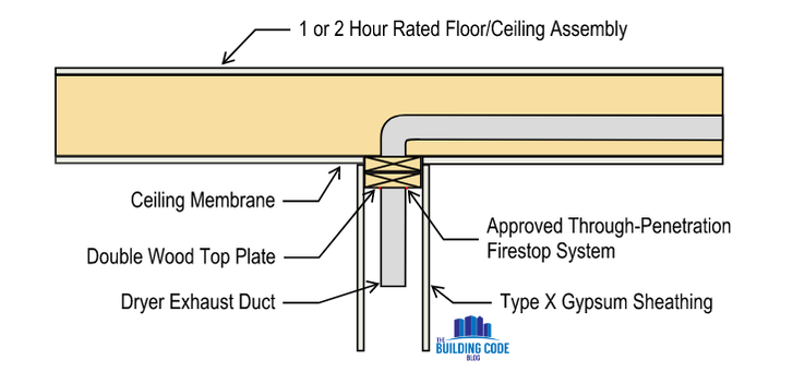 Detail showing the membrane penetration permitted by IBC 717.6.2.2, Exception 2. Before we get into those exceptions, though, it’s important to point out that running the dryer exhaust duct through a wall and into the ceiling cavity presents us with another code question: how do we address the intersection of the wall and rated floor/ceiling assembly? If the top of the wall is located completely below the ceiling membrane of the rated floor/ceiling or roof/ceiling assembly, there is no issue. However, this arrangement is difficult to construct, particularly in wood construction, as it would require a continuous ceiling running past the top of the wall. Most of the time, the top of the wall interrupts the ceiling membrane, meaning the ceiling stops on one side of the wall and continues on the other side. This arrangement would itself be considered a membrane penetration of the floor-ceiling or roof-ceiling assembly, even without a dryer duct present. IBC Section 714.5.2 Exception 7 addresses this exact situation: The ceiling membrane of a maximum 2-hour fire-resistance-rated horizontal assembly is permitted to be interrupted with the double wood top plate of a wall assembly that is sheathed with Type X gypsum wallboard, provided that all penetrating items through the double top plates are protected in accordance with Section 714.5.1.1 or 714.5.1.2 and the ceiling membrane is tight to the top plates.” This exception allows for the wall to interrupt the ceiling membrane as long as it is provided with a double wood top-plate that is tight to the ceiling and sheathed with Type X gypsum board. Note that this section does not require the wall to be rated. Additionally, the exception requires that the duct be protected in accordance with Section 714.5.1.1 or 714.5.1.2 (the same through penetration firestop sections referenced earlier). For my specific project, the building is a wood-framed structure, so there was no issue in providing a double top plate for each wall. In buildings of Type I or II construction, this would still be a valid approach as long as the wall itself is not a bearing wall and fire-retardant treated wood is used for the double top plate (IBC Section 603.1, Item 1.1). The final code section here, IBC Section 714.5.1.2, requires an approved through penetration firestop system with F and T ratings of at least 1 hour but not less than the rating of the floor itself. Exception 1 of this section eliminates the requirement for the T rating when the penetration is located within the cavity of a wall. This requirement forces us to find a listed fire-stop assembly that matches out proposed conditions. There are numerous assemblies available, particularly through companies such as Hilti or 3M. If you are tracking the code path through the mechanical code, the path is shorter, but the end result is the same. IMC Section 607.6.2, Exception 2 allows for the omission of a damper at the ceiling membrane penetration when the duct is protected in accordance with IBC Section 714.5.1.2, is located within the cavity of a wall and does not pass through another dwelling unit or tenant space. Note the subtle difference in section here compared to IBC Section 717.6.2.2 Exception 2 – the IMC takes you directly to the through penetration firestop requirement. See the flow chart below comparing the code path through both the IBC and IMC. 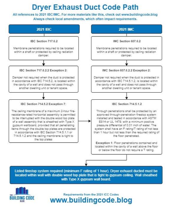 Comparison of the IBC and IMC code paths. Potential Challenge with Firestop System On the recent project where this issue came up, every firestop assembly for this configuration that I found stated that the dryer duct could be located within a wall, but when the wall was used, it had to be a minimum 1-hour rated wall. This was a challenge because the proposed configuration for my project involved the dryer exhaust duct running through an interior dwelling unit wall which was not rated. After a few hours of digging through the UL firestop database, I could not find a single listed firestop system that described a duct running through a non-rated wall and then into a 1-hour floor/ceiling assembly. This was a surprising result, as the IBC clearly does not require the wall to be rated when using Section 714.5.2 Exception 7. I ended up pursuing an Engineering Judgment to address the situation. ConclusionBoth the IBC and IMC provide code paths to route a dryer exhaust duct through wall, into a rated floor/ceiling or roof/ceiling assembly, and then out of the building. A listed firestop assembly is required to address the penetration of the duct through the ceiling membrane. If you happen to be running your duct through a rated wall, there are numerous firestop assemblies readily available for this configuration. If you are running the duct through a non-rated wall, you will likely need an engineering judgement. If you have found a listed firestop assembly that allows for a non-rated wall in this scenario, please let me know!
4 Comments
3/28/2023 02:22:27 pm
I don’t even understand how I stopped up here, but I assumed this put up
Juanita Harman
10/8/2023 02:29:33 pm
How close to the electric receptacle plug-in for an electric dryer can I put my dryer vent? Have you ever looked at creating a shaft for mechanical / bathroom exhaust and doing what is called a Sub-Duct? You can also create a shaft for Dryers and a shaft for Kitchen Exhaust. While bathroom or mechanical exhaust air can be dumped into the shaft, I believe the Kitchen and Dryer exhaust has to stay inside pipes inside of a dedicated shaft. Depending on your floor-to-floor height or your unit layout you can usually serve 4 or more units with one sub-duct or dedicated exhaust shaft. Where your ceiling heights are taller, luxury units, you can get more kitchens or dryers into a shaft. Dryers get dedicated ducts inside your vertical exhaust shaft. Kitchen and Bathroom exhaust can get combined. Check with your Mechanical Consultant on this. Sometimes these vertical shafts can save a billion small "hoods" on your building exterior, but requires a lot more coordination by your MEP Team. Leave a Reply. |
Categories
All
Archives
July 2024
|
The Building Code Blog
- Home
- Blog
- About
-
Tools
- Allowable Height & Area Calculator - Non-Separated Mixed Occupancy
- Allowable Height & Area Calculator - Separated Mixed Occupancy
- Average Grade Plane Calculator
- Calculated Fire Resistance for Wood Walls
- Fire and Smoke Damper Tool
- Fire Wall/Exterior Wall Intersection Tool
- Frontage Calculator
- IBC Occupant Load Calculator
- Plumbing Fixture Calculator
- Stair Pressurization Estimator
 RSS Feed
|
HomeAboutBlogContact |
Copyright © 2019-2024 The Building Code Blog
The views, opinions, and information found on this site represent solely the author and do not represent the opinions of any other party, including the author's employer and the International Code Council, nor does the presented material assume responsibility for its use. Local codes and amendments may vary from the code requirements described herein. Fire protection and life safety systems constitute a critical component of public health, safety and welfare and you should consult with a licensed professional for proper design and code compliance.
|